⚡ Q Factor Calculator
Calculate Quality Factor, Resonant Frequency, Bandwidth & Damping for RLC Circuits
| Circuit Type | Q Formula | Resonant Frequency | Bandwidth |
|---|---|---|---|
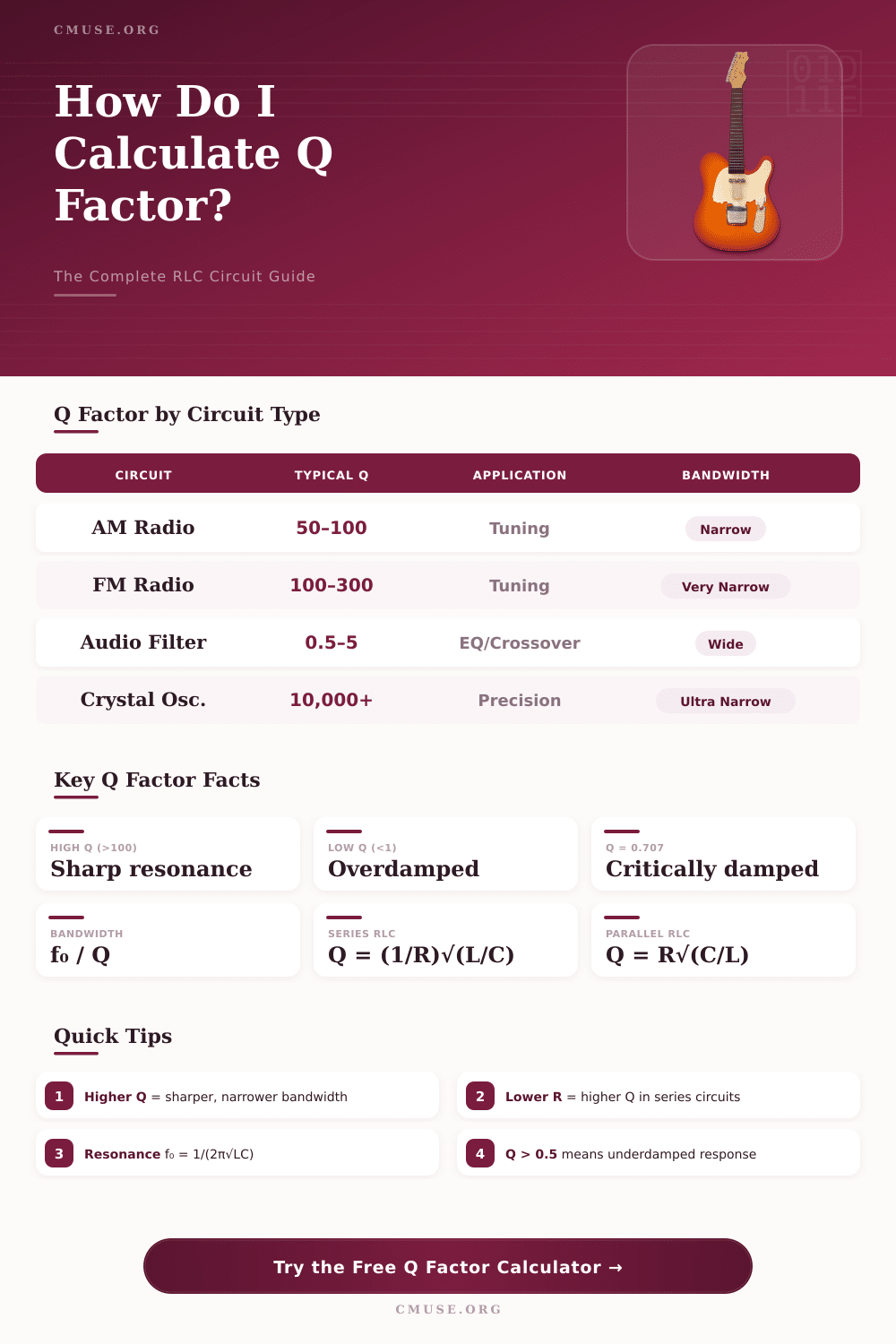
| Series RLC | Q = (1/R) √(L/C) | f₀ = 1/(2π√LC) | BW = R/L |
| Parallel RLC | Q = R √(C/L) | f₀ = 1/(2π√LC) | BW = 1/(RC) |
| From f₀ & BW | Q = f₀ / BW | — | BW = f₀ / Q |
| Damping Ratio | ζ = 1/(2Q) | ω₀ = 2πf₀ | α = ω₀/(2Q) |
| Energy (general) | Q = 2π × (Eₘ/Eₗ) | Per cycle | Eₘ=stored, Eₗ=lost |
| Q Value | Damping Ratio (ζ) | Response Type | Typical Use |
|---|---|---|---|
| Q > 0.5 | ζ < 1 | Underdamped | Oscillators, resonators |
| Q = 0.5 | ζ = 1 | Critically Damped | Step response, control |
| Q < 0.5 | ζ > 1 | Overdamped | Slow settling systems |
| Q = 0.707 | ζ = 0.707 | Butterworth (max flat) | Low-pass filters |
| Q = 0.577 | ζ = 0.866 | Bessel (linear phase) | Audio, signal integrity |
| Q = 1 | ζ = 0.5 | Underdamped moderate | Active filters (Sallen-Key) |
| Q Factor | Bandwidth (kHz) | Lower –3dB (kHz) | Upper –3dB (kHz) |
|---|---|---|---|
| 1 | 1,000 kHz | 500 | 1,500 |
| 5 | 200 kHz | 900 | 1,100 |
| 10 | 100 kHz | 950 | 1,050 |
| 50 | 20 kHz | 990 | 1,010 |
| 100 | 10 kHz | 995 | 1,005 |
| 1,000 | 1 kHz | 999.5 | 1,000.5 |
The Q factor are a measurement of the quality of a resonant system. The Q factor describes the ability of a resonant system to store energy compared to the amount of energy that it lose during one cycle. In electronic circuit, the Q factor indicates how precisely the circuit can select one frequency from a range of many frequencies.
Circuits with a high Q factor will have a narrow range of frequencies that it allow through the circuit, which allows for the circuit to select a specific frequency. Circuits with a low Q factor will allow a broader range of frequencies through the circuit, preventing it from selecting only one specific frequency. The resistors, inductors, and capacitors in the circuit can determine the Q factor of an RLC circuit.
What is the Q factor in circuits
Resistors cause circuits to lose energy, but inductors and capacitors is components that store energy. In a series circuit, using resistors with lower resistance will increase the Q factor of the circuit; lower resistance mean the circuit will lose less energy. In a parallel circuit, increasing the resistance will increase the Q factor, because higher resistance will allow the LC tank circuit to ring for a more longer period of time.
Resonant frequency can be calculated for an RLC circuit using the equation $f_0 = 1 / (2\pi\sqrt{LC})$. The bandwidth of an RLC circuit can be calculated by dividing the resonant frequency of the circuit by its Q factor. Because different application of circuits require different Q factors, there are different requirement for different types of circuits.
For example, AM radios has Q factors between 50 and 100, since the channels are only 10 kHz apart. FM radios have higher Q factors, between 100 and 300, because the channels are 200 kHz apart. Audio crossovers have low Q factors, between 0.5 and 5, so that the component will blend in with one another.
Quartz crystals have Q factors that are very high, often over 10,000, since they must remain at the correct frequency to function correct in computers and watches. A Q factor that is too high may cause instability in the circuit, but too low of a Q factor will prevent the circuit from rejecting interference. Another concept that relate to the Q factor is that of damping.
The damping ratio (zeta) is equal to one-half of the reciprocal of the Q factor. If the damping ratio is less than 0.5, the system is underdamped; an underdamped system will exhibit overshoot and ringing. If the damping ratio is equal to 0.5, the system is critically damped; it will reach its final state in the shortest amount of time without oscillation.
If the damping ratio is greater than 0.5, the system is overdamped; it is stable, but takes longer to reach its final state. Filter designer often choose specific damping ratios. For instance, people use a damping ratio of 0.707 for Butterworth filters, which are known for having a flat frequency response.
The components in a circuit will impact the Q factor of that circuit. Inductors that contains high-quality cores are used in circuits. High-quality cores will allow the inductor to store more energy.
Capacitors that use low dielectric absorption materials are used in circuits that require precision in timing. Low dielectric absorption minimize the capacitors impact on the Q factor. Using resistors with high resistance will decrease the Q factor of a circuit; high resistance will result in the circuit losing energy to the resistor.
Different component are affected by different temperatures. For instance, some types of capacitors will change in value if the temperature of the circuit change, while other types will remain the same. The Q factor can be measured by sweeping the frequency of the circuit, measuring the power at which the circuit emit energy at frequencies at which the power is halved, and calculating the Q factor as the resonant frequency of the circuit divided by the width of the frequency span at which the power is halved.