T-Line Subwoofer Box Calculator
Balance quarter-wave length, stuffing, driver area, and cabinet folds before you commit to a transmission-line build.
📦 T-Line Presets
📊 Design Inputs
📈 T-Line Spec Grid
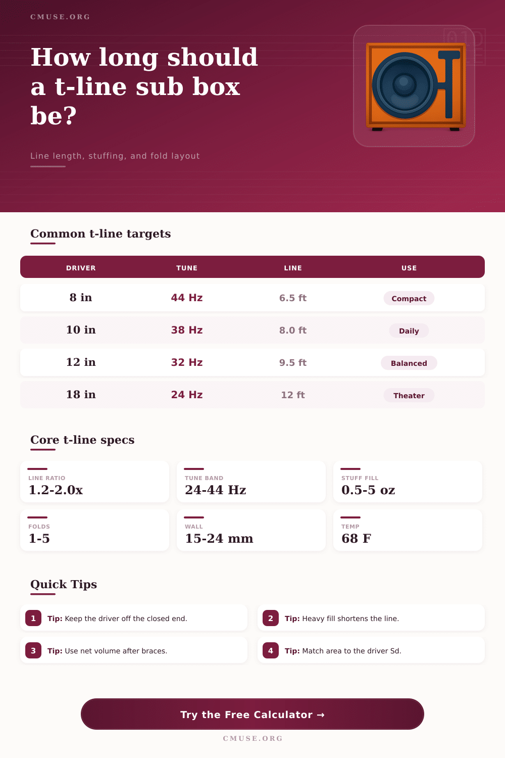
Common t-line targets
| Driver | Tune | Line | Use |
|---|---|---|---|
| 8 in | 44 Hz | 6.5 ft | Compact car or desk build |
| 10 in | 38 Hz | 8.0 ft | Daily bass and small rooms |
| 12 in | 32 Hz | 9.5 ft | Balanced home or truck output |
| 18 in | 24 Hz | 12 ft | Deep theater or large cabinet |
Line shape comparison
| Shape | Strength | Best use | Note |
|---|---|---|---|
| Rectangle | Easy fold | Most builds | Brace long spans well |
| Circle | Smooth flow | Tube lines | Harder to pack around |
| Triangle | Truck fit | Wedge boxes | Use the same area all through |
| Custom | Odd space | Special cabinets | Keep net area consistent |
Stuffing density guide
| Fill | Speed shift | Damping | Use |
|---|---|---|---|
| 0.5 oz/ft3 | -2% | Light | Brighter, shorter lines |
| 1.5 oz/ft3 | -6% | Balanced | Daily use and mild damping |
| 3.5 oz/ft3 | -12% | Heavy | Longer lines with softer peaks |
| 5.0 oz/ft3 | -16% | Very heavy | Only for long, well-braced lines |
Panel material guide
| Material | Density | Wall | Note |
|---|---|---|---|
| 15 mm birch | 640 kg/m3 | 0.59 in | Stiff and easy to brace |
| 18 mm birch | 630 kg/m3 | 0.71 in | Common for large sub boxes |
| 18 mm MDF | 730 kg/m3 | 0.71 in | Heavy, smooth, easy to seal |
| 24 mm MDF | 750 kg/m3 | 0.94 in | Massive panels for SPL builds |
Use this t-line subwoofer box calculator to balance quarter-wave length, stuffing, and line area so the cabinet lands closer to the target tune with fewer rebuilds.
A transmission line is a enclosure that acts as a long pipe for the speaker driver. Transmission lines is designed to be one-quarter of the wavelength of the target frequency. Transmission lines work by absorbing the resonance created by the speaker driver instead of reflecting those resonances back towards the speaker driver.
This is in contrast to a ported box, where the resonances are reflected back from the port toward the speaker driver. By calculating the length of the transmission line proper, an audio system will have tight and extended bass without any port noise. If the designer calculates the length of the transmission line incorrect, the audio system will have inconsistent bass response.
How Transmission Lines Work
The speed of sound within the transmission line can change based off air temperature and the damping material that the designer use within the line. In planning a transmission line, the designer must account for both end correction and air temperature shifts. To reduce the speed of sound within the line, damping material such as polyfill or long-fiber wool are used within the line.
By reducing the speed of sound within the line, the effective length of the transmission line is reduced. The amount of stuffing that is used within the line can be varied; lighter stuffing is used to maintain a punchy response from the speaker while heavier stuffings is used to lower the tuning frequency of the line. Using five ounce of stuffing per cubic foot of the transmission line will reduce the speed of sound within the line by 16%.
The diameter of the speaker driver will affect the design of the transmission line. The cone area of the speaker driver is referred to as Sd. The cross-section of the transmission line should be between 1.2 and 2 times the Sd of the speaker driver.
If the line is too narrow, it will choke the airflow from the speaker driver. If the line is too wide, it will waste the available space within the cabinet. A fold can be used in the line to allow it to fit within a smaller cabinet.
The straight transmission line is the most popular design for transmission lines but requires a very large cabinet to house the line. By folding the line two or three times, the designer can design the line to fit within a smaller cabinet. Each fold of the transmission line creates a segment of the line.
Each segment of the line require bracing to prevent the segment from flexing within the cabinet. Panel flexing of the cabinet wall will color the sound of the bass response from the speaker. To reduce panel flexing, thick materials can be used to construct the cabinet walls and bracing.
Baltic birch is a very stiff material while medium-density fiberboard (MDF) is a very heavy material. The temperature within the transmission line will impact the speed of sound within the line. The speed of sound within hot air is faster then in cold air.
Because the tuning of a transmission line is based upon the speed of sound, using hot air will shift the tuning frequency of the line higher. Using cold air will shift the tuning frequency of the line lower. The placement of the speaker driver within the line is also important.
The driver should be set back from the closed end of the transmission line. A standard practice is to set the driver back 20 to 25 percent of the total length of the transmission line. This prevent the first harmonic of the speaker cone from reflecting into the transmission line.
There are some common pitfall when building a transmission line. One pitfall is to not include bracing for long segment of the transmission line. Another pitfall is to not account for the displacement of the speaker driver basket when calculating the total volume of the transmission line.
If the designer ignores the displacement of the speaker driver, the volume calculation for the transmission line will be incorrect. Finally, the transmission line should be tested for proper construction. One test is to perform an impedance sweep of the transmission line.
When performed proper, the impedance sweep will reveal a dip in the impedance at the tuning frequency of the transmission line. The presence of a clean dip at the tuning frequency indicates that the line is constructed proper. Its important to realize that there are alot of ways to go wrong.
Youll need to be careful with teh measurements, because if you dont, the results could of been much worse. Actually, making mistakes is naturaly part of the process.