Class E Amplifier Calculator
Estimate optimum load, shunt capacitance, and series inductance for idealized RF Class E amplifier stages.
🔌 Presets
📏 Inputs
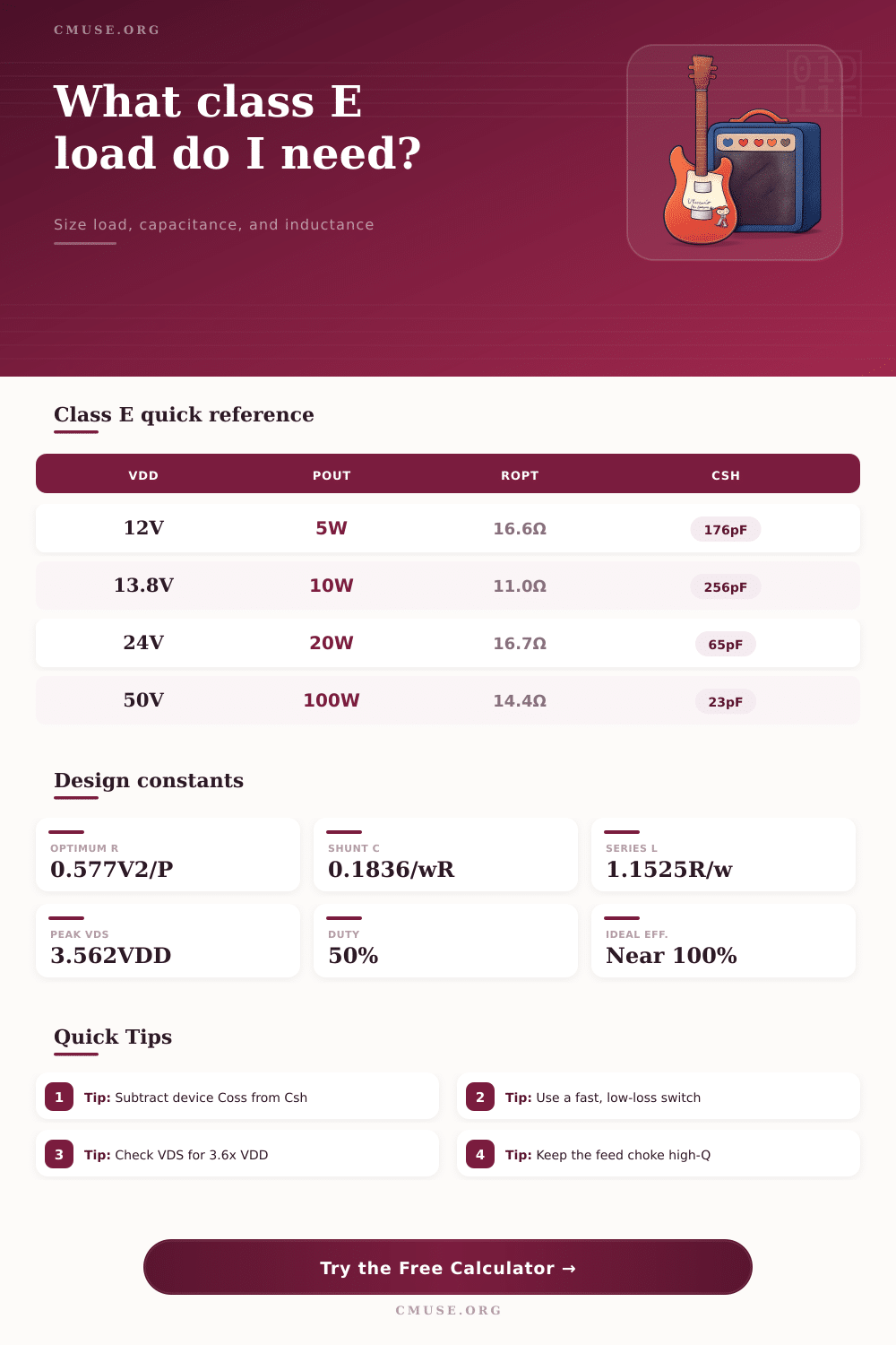
| Scenario | VDD | Pout | Key value |
|---|---|---|---|
| HF 5W | 13.8V | 5W | Ropt 22.0Ω |
| ISM 10W | 12V | 10W | Csh 210pF |
| Wireless 20W | 24V | 20W | L 12.7uH |
| Broadcast 100W | 50V | 100W | VDS 178V |
Ideal Class E equations assume a 50% duty cycle and lossless components. Real builds need margin for device capacitance, choke loss, and PCB parasitics.
Class E amplifier operates in switching rule. Similarly to Class D amplifiers, it works by means of switching. Even so, the nets for the load are especially designed to minimize losses during switching and lead the energy from shunt transistor output capacitance to the load The dynamic loadline of such amplifier is reached by means of fit harmonic impedances in the transistor output.
You separate harmonic final conductors in title of switching amplifiers as Class D, E, F and alike.
How Class E Amplifiers Work
Amplifiers of Class D and E switch their output element. The proportion of time, when it produces, can range by means of pulse-width modulation, what gives the wanted output power. In Class E amplifier the input simply switches the swith between shutoff and start, so the amplitude form of the input signal do not matter, if it only quite a lot switches it.
The basic notion of that amplifier consists in modeling of the active switching element, for instance transistor or MOSFET, as linear linkup of two bits. One bit is ideal switch. The other is parasitic net with capacitors, spools and resistors bound to it.
Practically Q range between 3 and 10, what is not enough to stop harmonic flows in the load. Basic Class E amplifier requires filter between the serial resonant circuit and the load for the needed harmonic repression. The reactance of the Class E load in working frequency are not zero and match the load resistance.
Class E amplifier has very narrow bandpas. The Q of the output spool seriously affects the efficiency. Ideally you use fat or air-core spool, that is suspended by the PCB and quite a lot distant from the case.
Class E RF power amplifiers do not like amplitude changes of the signal, so alone they answer only for amplifying constant envelope signals.
Even Class E RF amplifiers with some watts can generate voltage spikes in more than 100 volts. Build one from scratch require design of the circuit for the wanted power in wanted frequency from wanted input voltage on 50 ohm load. The switch indeed controls the output waveform in frequency and amplitude.
The DC pulses smooth to AC by means of spools, capacitors and the output filter. One mode to identify electrical attributes of various amplifiers are the class according to circuit arrangement and wayofoperation.