70V Speaker Calculator
Calculate distributed speaker transformer taps, total amplifier load, reserve headroom, wire voltage drop, current draw, and equivalent impedance for 70V audio lines.
🔊 Distributed Audio Presets
Use these presets as starting points for commercial background music and paging zones. The calculator sums transformer tap watts, estimates two-conductor wire loss, and checks whether the selected amplifier has enough clean reserve.
⚙ Line, Tap, and Amplifier Inputs
📊 Current Project Spec Grid
🎚 Constant-Voltage System Comparison
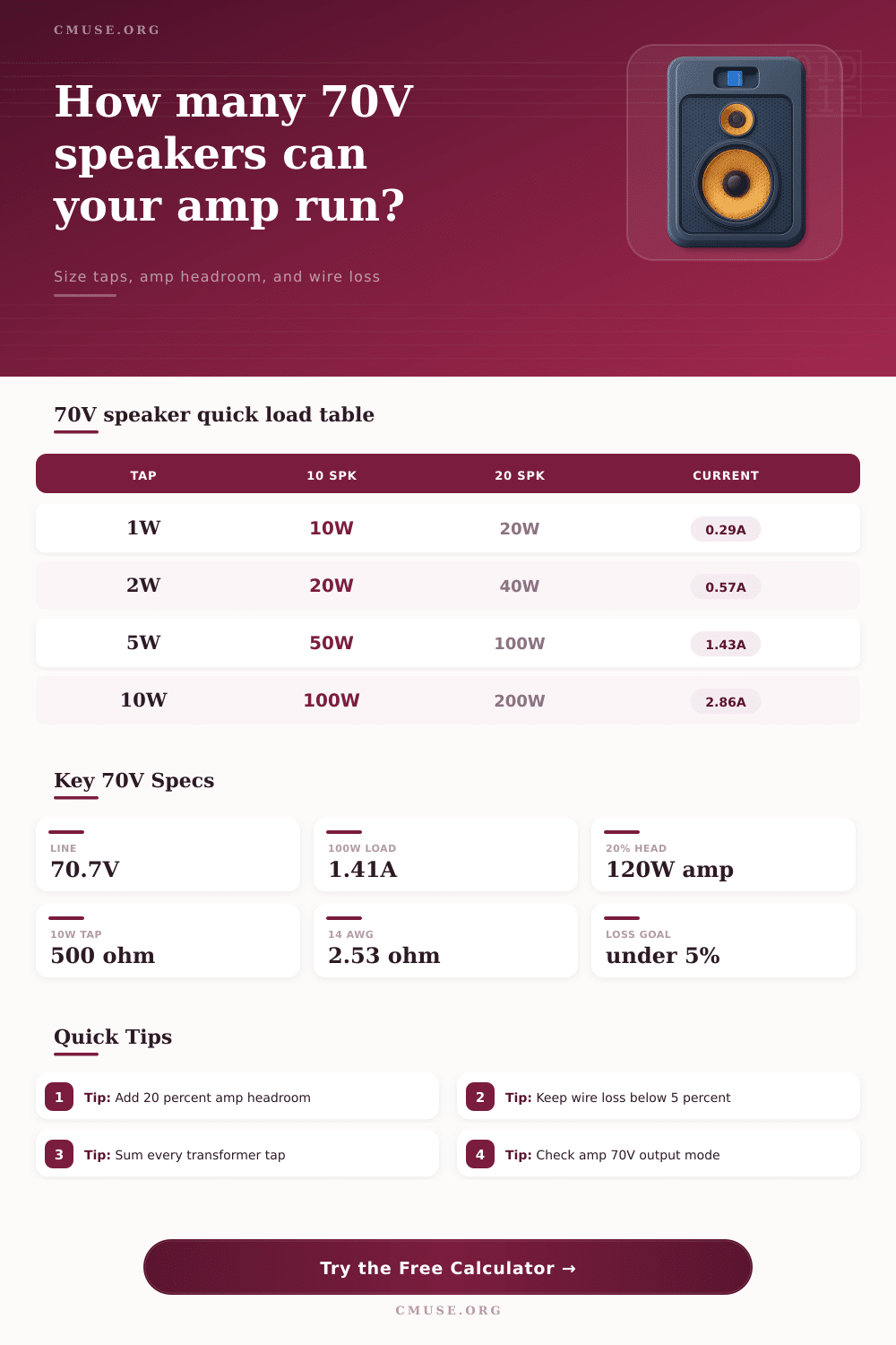
📐 Transformer Tap Reference
| Tap Setting | Equivalent 70V Impedance | 10 Speakers | Typical Use |
|---|---|---|---|
| 0.5 W | 9,998 ohms | 5 W total | Quiet paging, restrooms, very low background level |
| 1 W | 4,998 ohms | 10 W total | Soft corridors, offices, low-level announcement zones |
| 2 W | 2,499 ohms | 20 W total | Classrooms, retail aisles, moderate paging |
| 5 W | 1,000 ohms | 50 W total | Background music, restaurants, lobbies, patio fill |
| 10 W | 500 ohms | 100 W total | Louder foreground zones, larger ceiling speakers |
| 15 W | 333 ohms | 150 W total | High-output areas, small gyms, noisy rooms |
🔌 Wire Gauge Loss Reference
| Wire Gauge | Copper Ohms / 1000 ft | Best Fit | Design Note |
|---|---|---|---|
| 18 AWG | 6.385 ohms | Short low-wattage branches | Use carefully on long runs or high speaker counts. |
| 16 AWG | 4.016 ohms | Typical small commercial zones | Good default for moderate 70V background systems. |
| 14 AWG | 2.525 ohms | Longer corridors and higher loads | Often chosen when voltage drop matters. |
| 12 AWG | 1.588 ohms | Long trunk runs | Reduces line loss before smaller branch drops. |
| 10 AWG | 0.999 ohms | Very long or high-power trunks | Large cable can be harder to terminate at speakers. |
💪 Amplifier Headroom Guide
| Headroom Target | Formula | When It Fits | Risk Level |
|---|---|---|---|
| 10% | Tap load x 1.10 | Voice paging with predictable levels | Tight reserve |
| 20% | Tap load x 1.20 | Most background music plus paging zones | Normal reserve |
| 30% | Tap load x 1.30 | Foreground music or mixed-use spaces | Comfortable reserve |
| 50% | Tap load x 1.50 | Noisy spaces, horns, future expansion | High reserve |
🏢 Common Distributed Audio Scenarios
| Scenario | Speaker Layout | Typical Tap | Amplifier Planning Note |
|---|---|---|---|
| Coffeehouse Background | 8 ceiling speakers | 3 W to 5 W | Use 20% headroom and keep patio branches separate if possible. |
| Retail Aisle Paging | 18 to 30 speakers | 1 W to 2 W | Low tap settings allow many speakers on one modest amplifier. |
| Hotel Corridor Run | 20+ ceiling speakers | 0.5 W to 1 W | Long wire length usually drives the gauge decision. |
| Warehouse Horn Line | 6 to 12 horns | 10 W to 15 W | High taps need more amplifier reserve and thicker trunk cable. |
💡 Practical 70V Speaker Tips
When you begin to think about distributed audio systems, you have to determine the amount of power that will be required to fill the space even. The power requirements must be determined so that you dont purchase an amplifier that is too large for your system’s requirement (which would waste money), or that you will experience distortion from your speaker at high volumes. Before you can determine the amount of power that will be required, you must first calculate the total load that each of the individual speaker within your system will create.
Each speaker within a 70V line system will draw a certain amount of power based upon the setting of its transformer tap. The amplifier that you purchase will have to be able to handle not only the power that are drawn by the speakers within your system, but also some additional power as a reserve. This reserve power will allow your music and announcement program to remain clean and distortion-free when the speakers is playing at high volumes within the space.
How to Calculate Power Needs for a Distributed Speaker System
To calculate the total load of your system, you can simply add the power level of all of the individual speakers within your distributed system. However, you must also account for the voltage of the line that is used in your system, the length of the cable that are run to each speaker, and the amount of headroom that you wish to provide for your system. For instance, if you have twelve speaker within a zone, and each speaker is set to a transformer tap of 2 watts, the total power of the speakers is 24 watts (12 speakers x 2 watts).
However, you will need to add in headroom for your amplifier and account for the power that is lost within the running of the cables that distribute the audio signal to each speaker in your zone. The power that is lost within the cables can be accounted for within the power calculations for your system. The current that travels from the amplifier to the speakers also travels back to the amplifier along the same cable run.
The longer the cables, or the thinner the gauge of the cables that are run to each speaker, the more power that is lost due to the resistance within the cables. For these reasons, the wire loss is a small calculation when dealing with short cable runs to speakers with low transformer taps. However, the factor of wire loss become a significant calculation when running the system to long corridors of rooms, or to rooms that require high transformer taps to each speaker.
The calculator that is available will calculate the mathematical equation for you once you have entered the number of speakers that you wish to include in your distributed audio system, the transformer taps of each speaker, the distance that the cables will run one-way from the amplifier to the first speaker in the system, and the gauge of the wires that will be used to distribute the audio signal to each speaker. Based on these initial calculations, the distributed audio system calculator will provide the total load of the system, the current that will flow in the system, the impedance of the system, and the size of the amplifier that is required to efficient manage the power of each speaker. Each of these calculations can be used to compare the requirements of the system to the capabilities of your potential amplifier for the system.
This ensures that you will not guess if the amplifier that you are purchasing is large enough to handle the power requirement of each speaker in the distributed audio system. Distributed audio systems that are used for background music and paging may have different requirement for headroom within the system. For example, areas in a retail environment that have relatively low background music and low background noise level may use a headroom setting of 20% for its speakers.
However, areas that may contain loud background noise, such as small gyms or lobbies, may require a headroom of 30% or more to account for loud announcements. It is also important to consider the future of the system in relation to the size of the amplifier that is purchased for the system. For instance, if you are installing a distributed audio system in a home that may later have additional room that are to be outfitted with speakers, it may be best to purchase an amplifier that has additional headroom and additional current capacity to account for any additional speaker that may be installed in the future.
Purchasing an amplifier that does not have enough headroom for the current speakers within the system, and which can handle the current load of those speaker, will require you to purchase an additional amplifier for that system in the future. Another of the factor in the consideration of distributed audio system is understanding how the transformer taps relate to the system. Higher transformer taps will draw more current from the amplifier for the same level of line voltage.
Current that is increased will allow the system to produce louder sound from each speaker, but will also increase the loss of that current within the cables that distribute the audio to each speaker. For these reasons, zones that has speakers with high taps may require different models of amplifiers than zones that have speakers with low taps. Furthermore, low transformer taps allow for more speaker to be placed along the same run of wire, which is beneficial for long corridors of rooms.
Another consideration of distributed audio systems is the voltage of the line that will be used (70V, 100V, or 25V). Higher line voltages will allow for less current to travel through the wires from the amplifier to the speakers to deliver the same amount of power. Because current loss is reduced, higher line voltages allow for thinner wires to be used in the distributed audio system. The majority of commercial distributed audio systems in North America use 70V line.
However, many distributed audio systems that are installed internationally use 100V lines. The distributed audio system calculator that is available can be used to calculate the system requirements for each of these line voltage; simply changing the voltage allows you to see how the system current and amplifier size change with different line voltages. One mistake that an installer may make is to enter the round-trip distance for the audio signal from the amplifier to the speakers into the one-way distance field.
The audio signal travels along the wire from the amplifier to the speakers, but it also travels back along the same wire to the amplifier. Thus, the one-way distance that should of been entered into the distributed audio system calculator is half of the total distance of the cables; the calculator will automatically double that value internally to calculate the total resistance within the length of the cables. The voltage that is delivered to the speaker that is the most distant from the amplifier will allow you to determine if the settings of the transformer tap will produce the correct sound levels throughout the entire system.
Mistakes that can be made when calculating distributed audio systems are usually the result of underestimating the total load that will be created by each speaker in the system, or underestimating the headroom that will be required to accommodate the needs of the rooms in the system. For instance, an individual may undercount the number of speaker that are currently in the system, but that will be installed in the future. Furthermore, an amplifier that is chosen to exactly match the calculated load of the system may sound strained when playing at high volumes of music.
An extra margin of headroom ensure that the system will work correctly. The outcome of correctly calculating and installing a distributed audio system is a zone in which each speaker will produce the same level of sound as each of the other speaker in that zone. Furthermore, ensuring that each calculation is correctly performed will ensure that the system remains within the operating parameter of the amplifier, and that the distributed audio system has enough headroom to accommodate the addition of more speaker in the future.
Thus, by correctly calculating the requirement of the system, you can ensure that your installation will be succesful.