3 Way Speaker Crossover Calculator
Estimate passive woofer low-pass, midrange band-pass, tweeter high-pass, and level padding parts for a three-way loudspeaker crossover.
🔊 Three-Way Crossover Presets
🎚 Crossover Inputs
📊 Spec Comparison Grid
🧮 Component Formula Reference
| Section | First-Order 6 dB | Second-Order 12 dB | Notes |
|---|---|---|---|
| Low-pass series coil | L = Z / (2 pi f) | L = 0.2251 x Z / f | Use for woofer top edge and midrange top edge. |
| Low-pass shunt capacitor | Not used | C = 0.1125 / (Z x f) | Placed after the series coil in a common starter layout. |
| High-pass series capacitor | C = 1 / (2 pi f Z) | C = 0.1125 / (Z x f) | Use for midrange bottom edge and tweeter bottom edge. |
| High-pass shunt coil | Not used | L = 0.2251 x Z / f | Placed after the series capacitor in a common starter layout. |
| Driver padding | Optional resistor | L-pad series and parallel | Calculated only when pad dB is above zero. |
🔌 Three-Way Band Reference
| Driver Band | Typical Crossover Range | Impedance Detail | Practical Check |
|---|---|---|---|
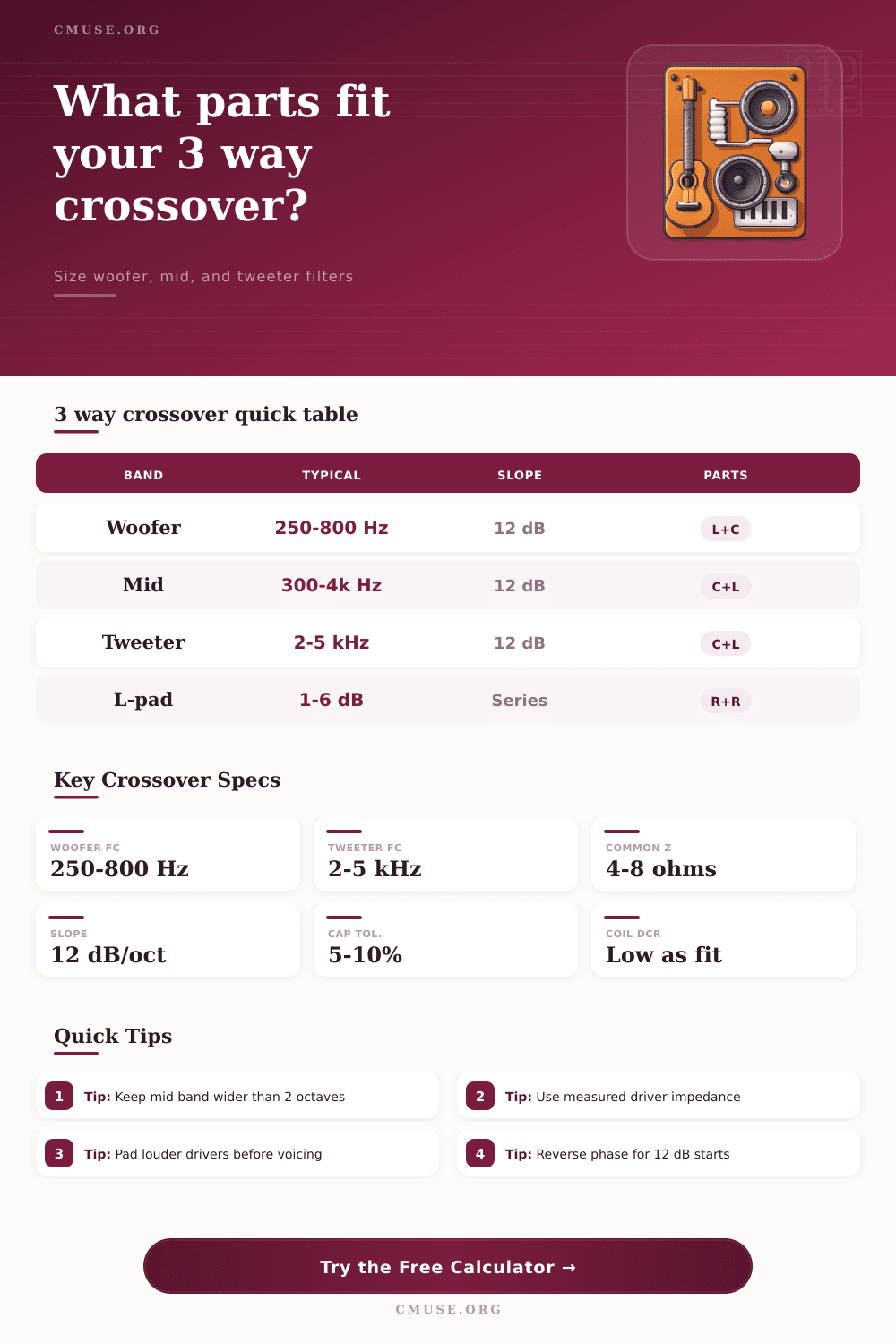
| Woofer | 250 to 800 Hz for many hi-fi three-ways | Nominal 4 or 8 ohms, but rising inductance matters | Keep breakup and beaming above the low-pass target. |
| Midrange | 300 Hz to 5 kHz depending on cone, dome, or horn | Use the impedance near both crossover points | A wider passband reduces steep filter pressure. |
| Tweeter | 2 kHz to 6 kHz for common dome tweeters | Never cross near the tweeter resonance peak | Use a crossover comfortably above Fs and power limits. |
| Horn tweeter | 4 kHz to 8 kHz when sensitivity is high | Often needs level padding | Pad before final voicing so the filter sees the expected load. |
| Car audio set | 800 Hz to 5 kHz is common for compact drivers | 4 ohm parts are larger current paths | Use higher power resistors and low DCR coils. |
📝 Preset Design Comparison
| Preset | Low Fc | High Fc | Typical Driver Set |
|---|---|---|---|
| Bookshelf 6.5 In 3-Way | 450 Hz | 3.2 kHz | 6.5 inch woofer, small cone mid, dome tweeter |
| Vintage Floorstander | 350 Hz | 2.8 kHz | 10 inch woofer, paper mid, soft dome tweeter |
| Nearfield Studio Monitor | 550 Hz | 3.5 kHz | Low distortion woofer, sealed mid, compact tweeter |
| Compact Dome Mid | 800 Hz | 4.5 kHz | Small woofer, dome midrange, dome tweeter |
| Large 15 In Woofer | 250 Hz | 2.2 kHz | Large woofer, strong mid, robust tweeter or horn |
| Car Audio 4 Ohm | 1.2 kHz | 5 kHz | Door woofer, small mid, compact tweeter |
📐 Component Selection Reference
| Part Type | Value Concern | Power Concern | Selection Note |
|---|---|---|---|
| Series woofer inductor | mH value controls low-pass point | Low DCR keeps bass damping tighter | Air-core is linear; laminated core can reduce resistance. |
| Shunt capacitors | uF tolerance shifts crossover frequency | Voltage rating should exceed amp peaks | Film caps are common; bipolar electrolytics can suit large values. |
| Midrange series parts | Both crossover edges affect vocal band balance | Midrange power is lower than woofer but still real | Keep layout spacing between coils to reduce magnetic coupling. |
| Tweeter L-pad | Attenuation changes effective load seen by filter | Use heat-rated resistors | Padding often stabilizes a bright or high-sensitivity tweeter. |
| Parallel notch or Zobel | Not included in this basic estimate | Depends on driver behavior | Add only after impedance and response measurements show the need. |
A crossover is an electrical circuit that can be used within a speaker system to route specific frequency to specific types of driver. Speaker systems typicly use different types of speakers and each type of speaker are designed to handle specific frequency ranges. If all of the speakers within a speaker system is directly connect to an amplifier, the amplifier will attempt to output all frequency ranges to each type of speaker.
As a result, the speakers that is not able to handle those specific frequencies will be damaged over time. For these reasons, it is necesary to employ a crossover circuit within the speaker system to route the correct frequencies to the correct driver. The designer can design the crossover circuit by employing component like inductors and capacitors.
How Speaker Crossovers Work
Inductors can be used to block high frequencies from reach certain drivers, and capacitors can be used to block low frequencies from reaching those drivers. Each component is not a perfect component, however, because each has an impedance that change based off the frequency of the electrical signal that pass through the component. If a simple nominal impedance is use for each component within the circuit, the resulting circuit may not accurately reflect the desired outcome; a crossover calculator can help to design the component values that will achieve the desired result with accuracy, rather than performing the complex mathematics calculations of Butterworth or Linkwitz-Riley filter alignments.
Each crossover circuit has a slope. A first order crossover will have a gentle slope and use only one component to filter the frequencies; however, it will allow for many of the unwanted frequencies to pass through the driver. A second order crossover will use a 12 dB slope, which provides for a steeper filtering of those unwanted frequencies than the first order crossover.
Second-order crossovers is often utilize due to there ability to provide protection for the tweeter and to provide better cleaning of the midrange frequencies. A potential drawback of using second-order crossovers is that they can introduce phase shifts between drivers; however, wiring the midrange speaker in a reverse polarity to that of the other can often correct these phase shifts. This reversal of polarity helps to even out the frequency response of the speakers.
Midrange speakers are often challenging to design due to the fact that the driver must be filtered from both high and low frequencies; it require a high-pass filter and a low-pass filter. If the frequency band for a midrange speaker is too narrow, there may be a gap in the sound that the system plays. To avoid this issue, the frequency band for the midrange speakers should be wide relative than the other drivers in the system, and having a wide frequency range for the speakers will help to avoid any filtering issue between drivers.
Another factor that must be considered in the building of a speaker system is the sensitivity of each driver. Tweeters are often more efficient than woofer drivers, leading to potential issues with tweeters being too loud relative to the other speakers in the system. To even out the sound of each speaker, level padding can be use.
Level padding may utilize an L-pad, which incorporates two resistors that will allow for the volume of a specific driver to be reduce. These resistors can be sized using a level padding calculator to avoid overheating the resistors. The values of the components can be calculate as described above.
However, there are other factors that relate to the components that should also be considered. For example, capacitors have tolerances in their values, and inductors have a direct current resistance (DCR). If the DCR of a woofer is high, the bass range can sound loose; therefore, air-core inductors can be used for the tweeter, and film capacitors can be used for the midrange speakers.
Each of these calculated values is merely a starting point; physical construction of the speakers and the rooms size can impact the sound that the speakers create. Thus, building the three-way speaker system involve calculating the components, building a prototype, and adjusting the sound that the system create.