3 to 1 Mic Rule Calculator
Check whether two microphones are far enough apart for the 3-to-1 rule, then estimate bleed level, path delay, phase risk, spacing advice, and inverse-square SPL drop.
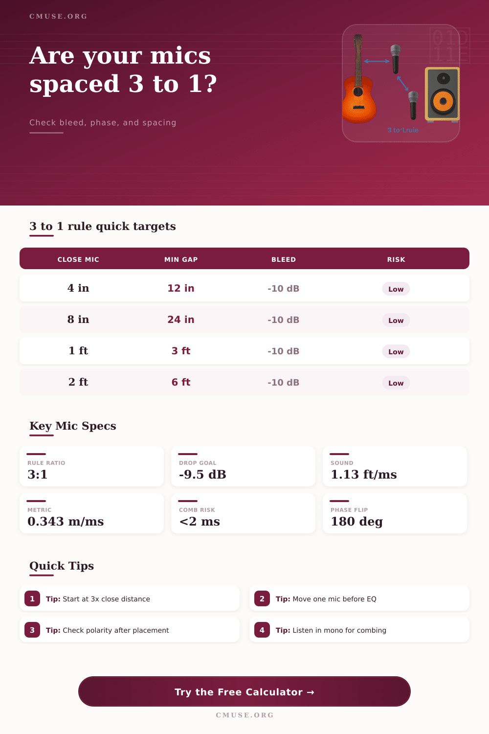
Choose a real recording setup to load starting values. The 3-to-1 rule says the distance between microphones should be at least three times the source-to-primary-mic distance, but angle, pattern, frequency, and spill level decide how forgiving the result feels.
Angle uses simple geometry: source-to-primary distance, capsule spacing, and spacing direction estimate the bleed path into the second mic. Real rooms add reflections, instrument radiation patterns, and preamp polarity, so use the result as a placement starting point.
Calculation Breakdown
Minimum 3:1 Spacing
Calculated Bleed Path
Bleed SPL Estimate
Recommended Spacing Angle
| Source To Mic | Minimum Mic Spacing | Distance-Only Drop | Common Use |
|---|---|---|---|
| 3 in / 8 cm | 9 in / 23 cm | about 9.5 dB | Very close snare, percussion, cabinet detail |
| 6 in / 15 cm | 18 in / 46 cm | about 9.5 dB | Vocal, guitar, horn, and tight spot mics |
| 12 in / 30 cm | 36 in / 91 cm | about 9.5 dB | Acoustic instrument pairs and ensemble spots |
| 24 in / 61 cm | 72 in / 183 cm | about 9.5 dB | Choir, piano, room, and stage-section spacing |
| Pattern | Helpful Angle | Rear Behavior | Placement Note |
|---|---|---|---|
| Cardioid | 90 to 180 degrees | Strong rear rejection | Good default for reducing spill between nearby sources |
| Supercardioid | 100 to 140 degrees | Small rear lobe | Aim nulls carefully; rear bleed can return if angled badly |
| Hypercardioid | 110 to 125 degrees | Clear rear lobe | Useful in tight spaces but less forgiving behind the mic |
| Omnidirectional | Distance only | No null | Needs more spacing or quieter bleed because pattern gives no help |
| Figure-8 | 90 degrees | Equal rear pickup | Side nulls can be excellent when aimed at the unwanted source |
| Path Difference | Delay At 68 F | First 180 Deg Frequency | Phase Meaning |
|---|---|---|---|
| 1 in / 2.5 cm | 0.07 ms | 6.8 kHz | Mostly high-frequency combing if levels are similar |
| 3 in / 7.6 cm | 0.22 ms | 2.3 kHz | Can hollow upper mids in mono blends |
| 1 ft / 30 cm | 0.89 ms | 565 Hz | Audible tone change when bleed is strong |
| 3 ft / 91 cm | 2.66 ms | 188 Hz | Starts to read as space if source levels differ |
| Setup | Close Distance | Starting Spacing | Primary Check |
|---|
The 3 to 1 rule are a guideline for placing two microphones so that the microphones dont pick up any overlapping signals from the same sound source. If the two microphones are too close to the sound source, each microphone will pick up the same signal from that source, but the signals will fight with each other once they reach the mixer. To avoid this, the distance between each of the capsules from the sound source must be roughly three times the distance from the sound source to the nearest microphone.
Thus, using the 3 to 1 rule will prevent comb filtering from occurring with the microphones, and it will prevent the sound from each microphone track from sounding thin when the tracks is combined. To calculate the distance at which each of the two microphones should be placed relative to the sound source, it is first necesary to enter several factor into a calculator. You must enter the distance from the sound source to the primary microphone into the calculator.
The 3 to 1 Rule for Placing Two Microphones
This distance from the source to the primary microphone will establish the baseline for calculating the placement of the second microphone. The spacing between each of the microphone capsules must be entered into the calculator. This spacing will establish the distance between the two microphones.
The angle between the microphones must be entered into the calculator. This angle will establish from which direction the microphones will pick up sound. Finally, the polar pattern of the microphones must be entered into the calculator.
For example, if the microphones are cardioid, they will reject sound from the side and rear of the microphone, but if they are omnidirectional they will offer no help in rejecting sound from other directions. Thus, for an omnidirectional microphone it is more difficult to achieve isolation from a sound source using the 3 to 1 rule than with a cardioid microphone. Finally, several additional factor will impact the functioning of each of the microphones when they are placed in a real room.
Bounces of the sound from the floor, ceilings, and walls into the second microphone will be picked up by that second microphone even if the polar pattern of the microphone does not reject sound from that direction. The temperature of the room will also impact the placement of each microphone because the speed of sound change with the temperature in the room. These factors must be considered when using the distance calculated by the calculator.
For instance, if the calculation within the calculator suggests a high risk of phase issues between the two microphones, that suggests that the sound from each of the microphones will arrive at each microphone capsule at such a time difference that the signals will cancel each other out at the frequency calculated. Problems with phase between the signals picked up by each microphone can be solved through the physical movement of one of the microphones rather than through the application of high-pass filters or equalization to the sound. Many engineers utilize the following process to utilize the 3 to 1 rule in their live sound or studio recordings: place the primary microphone into the location where the sound quality is the best; move the second microphone until the shared sound source no longer sounds thin when played back in mono.
Utilizing the calculator to determine where each microphone should be placed can make each of these steps significantly faster. Furthermore, the calculator will also estimate the amount of bleed through the second microphone into the first. This estimation will allow the engineer to determine whether or not the placement of the two microphones will work for the specific sound source that must be captured.
Furthermore, reference tables exist on the page that illustrates the distances that should be used between the capsules of two microphones for various sound sources and instruments; thus, the engineer does not have to re-enter each calculation for each instrument. The 3 to 1 rule is a guideline rather than a rule that must be followed. For example, for a live ensemble the engineers might want to allow for more bleed between the two microphones in order to allow for a more natural sound to reach the listener from the room, and to allow for better phase with the sound that is produced by the instruments that have low end frequencies.
In a multitrack recording session, however, the engineers might want to allow for the additional spacing between the microphone capsules that is required by the 3 to 1 rule so as to allow the mixing engineer more flexibility in creating the desired master track. However, the calculator cannot determine whether this additional isolation between the two sound sources is worth the change that will be made to the sound of the track. In addition to considering the factors related to the sound source to be recorded, additional decisions must be made regarding the polar patterns of the microphones.
For example, a supercardioid pattern will provide more rejection of sound from the sides of the microphone than a cardioid pattern, but it will also include a lobe that picks up sound from the rear of the microphone; this could be a problem for the second microphone if it isnt also pointed in that direction. The calculator will allow the engineer to determine if the rotation of the microphone will provide as much isolation from the sound source as moving the microphone itself. Furthermore, if figure eight microphones are used the null of the pattern can be aimed at the sound source that is creating the bleed; however, figure eight patterns are equally sensitive to sound from both sides of the microphone.
Thus, the figure eight patterns require careful placement into the environment and the sound source; the calculator can remove the guesswork related to the angles at which the figure eight patterns should be placed, but the calculator does not in any way replace the need for the engineers to listen to the sound that each microphone is creating. Another factor that impacts the placement of the microphones is the issue of phase problems between the two microphones. Phase problems between the microphones may be less noticeable when compressed sound is applied to the microphone signal; however, small differences in the arrival of the sound to each of the microphone capsules can result in noticeable flanging of the instrument signals once they are compressed.
Furthermore, the delay and phase calculations that the calculator performs will allow the engineers to determine if the timing differences between the two microphones will be small enough to avoid noticeable phase problems. If the phase risk level calculated by the calculator is high, one can move one of the capsules a few inches to avoid phase problems before the signal reaches the preamp. The impact of the temperature of the environment in which the sound is to be recorded will also have an impact upon the functioning of the microphones.
For example, placing the microphones in a cold room will impact the speed of sound that is created; slower movement of sound through the air will create more of a delay between the two microphone capsules. The calculator accounts for these changes in speed of sound; however, it is also necessary for engineers to use their memories of the impact of the humidity of the environment, the movement of the air within the room, and the presence of the audience to fine-tune the placement of the microphones. Thus, the calculator is a helpful tool in determining the placement of the two microphones, but engineers must use their own ears to verify that the placement of the two microphones is correct; understanding the trade-offs that will be made between sound isolation of the sound source from the microphones and the sound of each of the microphones will allow the engineers to make an informed decision regarding which compromise in sound quality is the best for that particular song.